A building facade lit with dozens of LED fixtures wired in long runs is a common setup for hotels, commercial towers, and large residential developments — and it’s also one of the more common places voltage drop shows up as a visible problem. Fixtures near the start of a wiring run often look noticeably brighter than fixtures at the far end, even when every unit on the run is the identical model. Keyida is an outdoor lighting manufacturer with 25 years of industry expertise. Reviewing how its products are specified can provide a practical reference for understanding voltage-drop considerations in large facade lighting installations.
Recognizing the Symptoms Before Assuming It’s a Fixture Defect
Voltage drop rarely announces itself directly — it shows up as a pattern of symptoms that can initially look like individual product failures. The most common sign is a gradual dimming effect along a wiring run, where fixtures closest to the power source appear at full brightness while those further away appear noticeably dimmer, even though every unit is drawing power from the same circuit. In fixtures that include electronic sensors or controls, insufficient operating voltage may also affect their behavior, depending on the design and minimum operating requirements of the electronics. If the voltage at the fixture falls outside the driver’s specified operating range, reduced output, flicker, or other performance issues may occur, depending on the driver design. Before replacing individual fixtures suspected of being defective, checking voltage at multiple points along the run is generally a faster and more accurate diagnostic step.
What Actually Causes the Drop
Voltage drop occurs because every length of wire has some electrical resistance, and that resistance causes a small amount of voltage to be lost as current travels through it. The longer the wire run and the higher the current draw, the more voltage is lost by the time it reaches the fixtures furthest from the source. This becomes especially relevant on large facade installations, where a single wiring run might extend well beyond what a residential installation would ever require, often stretching the length of an entire building elevation. Undersized wire gauge compounds the problem, since thinner conductors carry more resistance per foot than thicker ones. A run that was adequately sized for the original fixture count can also develop drop issues later if additional fixtures are added to the same circuit without re-evaluating the wire gauge for the increased total current draw.
Where Fixture Specifications Factor Into the Picture
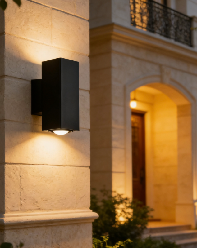
Reviewing an actual product specification helps illustrate one practical buffer against voltage drop: input voltage tolerance. Keyida’s outdoor wall lights motion sensor model A0696 is built with a die-casting aluminum housing and tempered glass cover, uses a CREE COB 2x5W LED chip with a KEDA driver, and is rated for an input voltage range of 85–265V AC at 50/60Hz. It carries an IP65 rating, measures Ø65 × W100 × H160 mm, and comes with a 3-year warranty. Its 85–265V AC input range indicates that the fixture is designed to operate across a broad input-voltage range, but this should not be treated as a substitute for proper voltage-drop calculations. The actual voltage available at each fixture still needs to remain within the driver’s specified operating range.
Operating under the Keyida name, the company produces this and other facade-suited fixtures from a 7,000㎡ manufacturing facility, with certifications including CE, RoHS, and SAA across its product range. For large-scale LED building facade lighting projects specifically, reviewing a fixture’s documented voltage tolerance alongside its physical placement plan is a reasonable step before finalizing a wiring layout, since the two considerations are directly connected.
Practical Fixes: Home Runs, Power Injection, and Wire Gauge
A common way to reduce voltage drop on a large facade installation is to divide a long branch circuit into multiple shorter runs, each supplied from an appropriately sized home run or distribution point. This is sometimes called power injection, and it effectively resets the voltage available at multiple points along the facade rather than letting it decline continuously from one end to the other. Increasing wire gauge on longer runs is another common approach, since thicker conductors reduce resistance and therefore reduce the amount of voltage lost per foot. Standard voltage drop calculators, widely available from electrical supply manufacturers, can help estimate the expected drop for a given wire gauge, run length, and current load before installation begins, which is generally more reliable than adjusting wiring after fixtures are already mounted and symptoms have appeared.
Verifying the Fix After Installation
Once adjustments are made, checking voltage at the furthest fixture on each run — ideally under full load, at night, with all fixtures active — confirms whether the correction actually resolved the issue rather than just reducing it. A multimeter reading taken at the last fixture on a run, compared against the reading at the power source, gives a direct measurement of total drop across that specific circuit. This kind of verification is particularly useful on large facade projects, where visual inspection alone can be misleading if ambient light or building shadows make brightness differences harder to judge accurately by eye.
A Practical Summary
Voltage drop on large facade installations is generally a wiring and load-planning issue rather than a fixture quality issue, though fixtures with a wider input voltage tolerance do provide additional margin before symptoms become noticeable. Diagnosing the pattern correctly, reviewing documented product specifications, and correcting the wiring layout with appropriately sized home runs tends to resolve the underlying cause more reliably than replacing individual fixtures suspected of being defective.